
Hardware-in-the-Loop (HIL) simulation is a powerful and widely adopted method for testing and validating the complex control systems that govern microgrids and renewable energy systems. By connecting physical controllers to a highfidelity, realtime digital model of the power system in RTSIM, HIL creates a digital twin—a safe, controlled environment where engineers can test, refine, and optimize performance before field deployment.
Solution Benefits
-
Risk-free development Identify and correct control system issues in the lab before they impact real-world operations.
-
Controller validation Test voltage and frequency regulation, load balancing, and seamless transitions between gridtied and islanded modes.
-
Islanded Mode Testing Validate seamless transitions between grid-tied and islanded operation, including reconnection logic.
-
Renewable integration Simulate variable wind and solar outputs to assess system stability and improve adoption of clean energy sources.
-
Black Start and Resilience testing Validate the microgrid’s ability to restart control and power systems after a full shutdown.
-
DER coordination and Energy balancing Optimize coordination between local generation (wind, solar, diesel), battery storage, and dynamic load conditions.
-
Cyber-Physical Risk Assessment Safely simulate cyberattacks and cascading failures to assess system resilience and response strategies.
Hardware-in-the-Loop (HIL) Testbed for Microgrid and Renewable Energy Systems
Hardware-in-the-Loop (HIL) simulation bridges the gap between software modeling and physical commissioning by connecting real control hardware (e.g., microgrid controllers, inverter control units, battery management systems) to a real-time digital twin of the power system in RTSim. This allows engineers to test control logic, fault response, and system interactions in a safe, repeatable lab environment.
Power Hardware/Controller Hardware in the Loop Testing
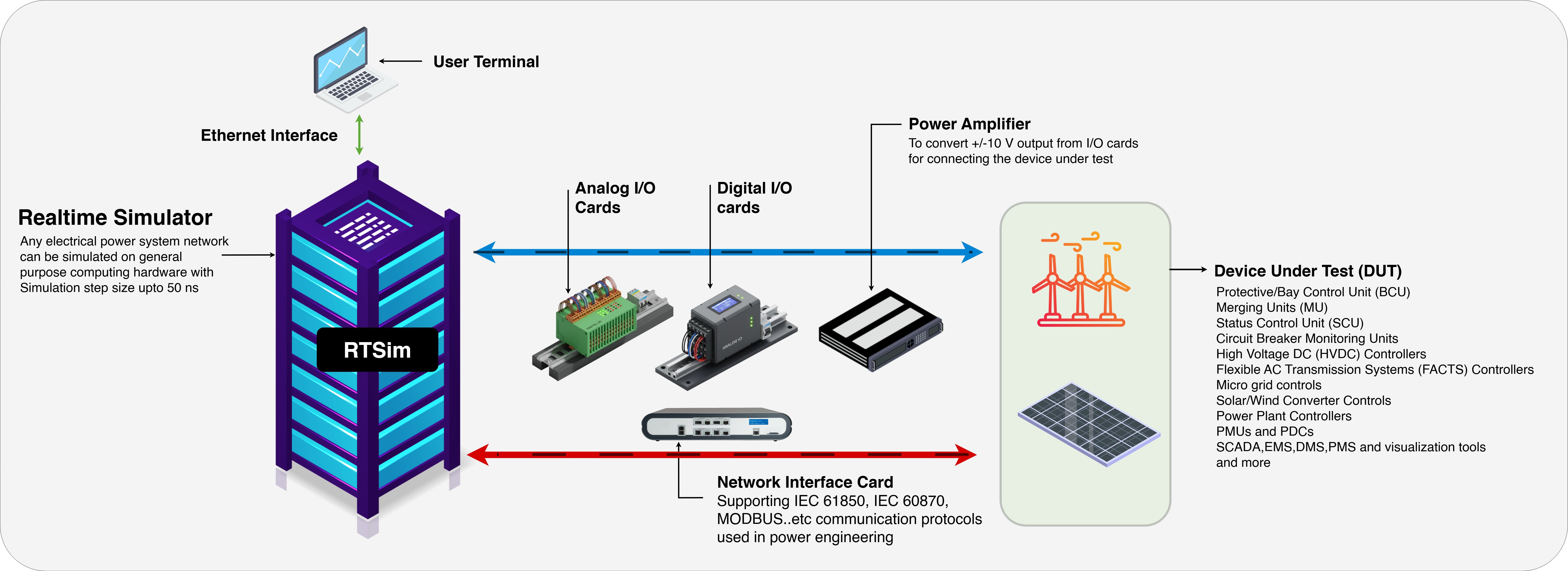
Analog & Digital I/O
- Simulated voltage, current, and breaker status signals are fed into the controller’s input channels.
- Trip commands, setpoints, and dispatch signals from the controller are fed back into RTSim to update the system state.
PWM & Gate Signal Capture
- For inverter and converter testing, the controller’s PWM outputs are captured and used to drive the simulated power electronics in RTSim.
- This enables validation of switching behavior, modulation strategies, and fault response.
Communication Protocols
- Support for Modbus, CAN, IEC 61850, DNP3, and proprietary Ethernet protocols ensures real-time data exchange between RTSim and controller.
- Enables testing of SCADA integration, remote diagnostics, and DER coordination.
Renewable Resource Emulation
- Simulate solar irradiance and wind speed profiles in RTSim to test MPPT algorithms, ramp-rate control, and curtailment logic.
- Controllers receive realistic generation profiles and must adapt dispatch and storage strategies accordingly.
Battery System Modeling
- Emulate battery voltage, SOC, temperature, and charge/discharge dynamics in RTSim.
- Validate BMS logic for energy flow control, thermal management, and fault handling.
Grid Event Injection
- Simulate voltage sags, frequency excursions, blackouts, and reconnection events in RTSim.
- Validate transitions between grid-tied and islanded modes, black start capability, and dynamic load balancing.
Why It Matters